
Understanding biomechanics plays a large role in orthopedics. It is particularly useful for describing the behavior of bones under stress and important in understanding orthopedic implants. Approaching biomechanics first requires an understanding of basic biomechanical terms.
Loading
Simply means applying a force to an object. In biomechanics there are three basic methods of loading (Figure 13). Compression involves a stress that compacts the structure. Tension involves pulling the structure. Finally, shear involves pushing the structure eccentrically. Torsional loading involves the twisting of a structure, however, when seen in cross section this is essentially the same as shear for an individual unit of the structure. These different means of loading will substantially impact the way a structure behaves. For bones, these loading characteristics produce vastly different, but predictable fracture patterns (Figure 14).
Figure 13
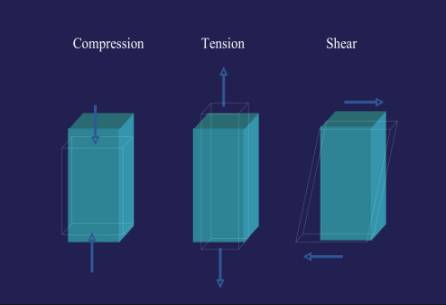
Figure 14
Anisotropic & Isotropic
This describes a characteristic of a material that behaves differently depending on the direction of loading. For example, a femur has tremendous strength when loaded in compression but will fail with much less force in torsion and is weakest in shear. This is opposed to isotropic materials that behave the same no matter which direction they are loaded. Most metals demonstrate isotropism.
Stress & Strain
Stress and strain are terms used to describe the ability of an object to withstand external forces. When a force is applied to a material (for example, a metal plate) the internal structure of the material will undergo changes to resist that force. These changes will directly counteract the applied force. The internal force that resists the applied force is called stress. The deformation of the material caused by the external forces is called strain.
Stress = Force/Area
Stress can be calculated by dividing force by area and is expressed in units of megapascals (MPa). In practical terms this means that as a load (such as a tensile force) is applied to a material (such as a metal plate), the plate will elongate. Strain is strictly defined as the relative measure of the deformation of a body as a result of loading. In simple terms this describes how an object reacts to being loaded. Stress and strain can be determined and graphed together to give useful information on the properties of materials in a diagram called a stress-strain curve. Stress is placed on the y-axis and strain is placed on the x-axis (Figure 15).
Figure 15
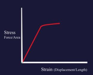
Initially, this elongation takes place with a linear relationship to the applied load and can be graphed as a straight line on a load/extension curve. Hooke’s law dictates that this relationship remains directly proportional through the linear portions of the stress-strain curve. This is important in that it allows one to calculate the exact deformation of a plate with a given stress. Practically this allows designers to create devices that will provide adequate support under stress and allows for comparison of materials (Figure 16). However, once a certain strain is reached, the material begins to deform and will no longer assume it’s original shape when the stress is released. This point is called the yield point (see below).
Figure 16
Young’s Modulus of Elasticity
Young’s Modulus of Elasticity
This number defines the relationship between stress and strain for a given material during the linear aspect of the stress-strain curve. Basically, it describes the elasticity of a material. It is calculated by dividing the stress by the strain, or visually it is the slope of the line created on a stress-strain curve through the elastic portions of the curve. Components with high moduli are stiff like stainless steel; on the other hand, low moduli describe soft materials like ultra-high molecular weight polyethylene (a material used in joint replacement inserts.) Young’s modulus is a useful comparison of material used in orthopedics today (Figure 17 & 18)
Figure 17
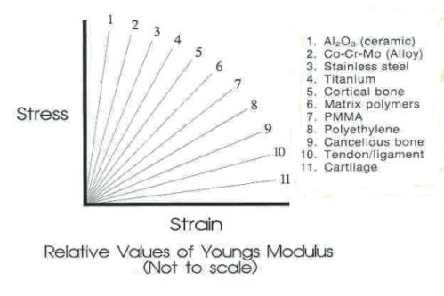
Figure 18
Common values for Young’s Modulus
| Stainless Steel | 200 |
| Titanium | 100 |
| Cortical Bone | 7-21 |
| Bone Cement | 2.5-3.5 |
| Cancellous Bone | 0.7-4.9 |
| UHMW-PE | 1.4-4.2 |
Hooke’s Law
A law stating that stress and strain are directly proportional. This is graphically represented by the fact that the initial portions of a stress-strain curve are linear. This law is the basis for predicting the biomechanical properties of implants.
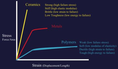
Toughness
A term used to define the amount of energy a substance can absorb before failure. For example, this term denotes how much energy a hip can absorb before it fractures. For brittle materials, such as ceramics, this number is low meaning that they cannot absorb much energy before chipping or cracking. On the other hand, rubber is very soft (not brittle) and tough; meaning rubber can absorb large quantities of energy before it breaks. Graphically represented by the area under the curve on a stress-strain diagram (Figure 19). Ceramics are notoriously brittle and require very little strain before failure which results in chipping and cracking. Ultra-high molecular weight polyethylene (UHMWPE) is extremely tough and therefore frequently used in arthroplasty.
Yield Point
The point along a stress-strain curve that describes when deformation of a material under stress stops occurring along a linear path (Figure 19). This point coincides with the portion of the curve when plastic deformation begins to occur and the material stops proceeding along the elastic region of the curve. Essentially, this means the material begins to change from its original shape and can no longer return to that form.
Figure 19

Creep
The time-dependent process by which slow continuous deformation will begin to occur under a constant stress.
Stress Relaxation
The process by which a material will deform to relieve stress when placed under constant strain.
Ultimate Tensile Stress
The point at which failure of a material occurs after only one cycle. Denoted in Figure 19 as the failure Point
Fatigue
A material subjected to multiple loading cycles will fail at a level far below the ultimate tensile stress. An example of this can be seen with the sequential bending of a paper clip to the point where is ultimately breaks.
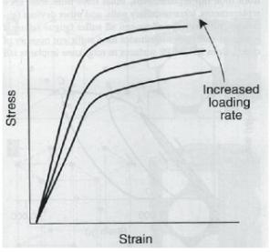
Viscoelasticity
This term describes a material that demonstrates time-dependent behavior. In other words, a material that reacts differently when loads are exerted over different time periods (Figure 20). Bone is a perfect example of a viscoelastic substance because the stress-strain character depends on the rate of applied load. Bone loaded very quickly will fail at a much lower point than bone loaded more slowly. This property relates to a material’s ability to adjust to that load given time. This runs contrary to most metals; which behave the same under any loading rate.
Figure 20
Elastic Deformation/Plastic Deformation
Elastic deformation describes the ability of an object to return to its original shape after a load has been applied. One might think of a rubber band being stretched when loaded but returning to exactly the same shape when released. Plastic deformation describes a permanent deformation of a material that has been placed under a stress. To continue the example one could think of stretching the rubber band so far that it breaks and can no longer return to its original shape. Another example can be found in pediatric orthopedics with the “green stick” fracture. In this injury one cortex of the bone is broken and the other is plastically deformed to produce a bend in the cortex that will not spring back into place.